
An AIS transponder is largely a sealed box that either works or does not. The part of the installation that determines whether you see targets at twenty miles or at five is the antenna system, and it is also the part most often rushed. Two separate antenna problems have to be solved on a transponder installation: the VHF antenna that carries the AIS transmissions, and the GNSS antenna that gives the transponder its position.
One antenna or two
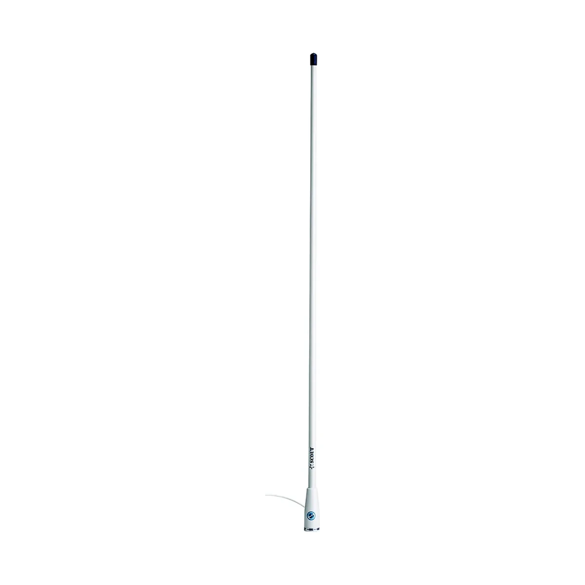
The VHF side can be handled in two ways. A dedicated AIS antenna is the simplest arrangement: a second VHF whip, tuned for the AIS frequencies rather than the voice channels, with its own cable run straight to the transponder. Digital Yacht's KS30 is a 1 m antenna tuned to 162 MHz and supplied with 5 m of RG58 and a BNC connector for this purpose. A dedicated antenna avoids any interaction between the radio and the transponder, and it is what you want if there is a free mounting point.
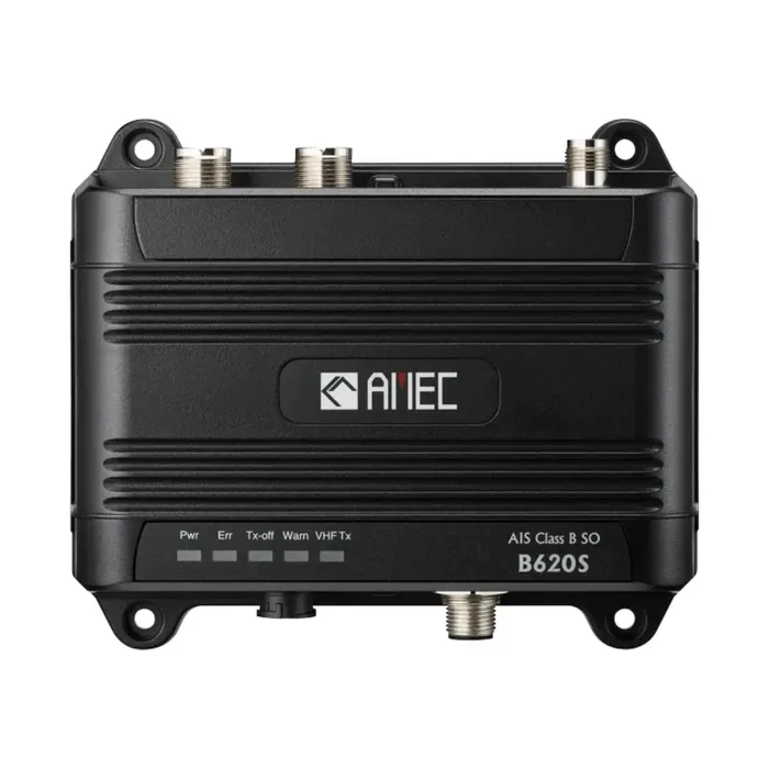
Where there is no free mounting point, a VHF splitter lets the AIS transponder and the VHF radio share one antenna. This can be a separate in-line unit or, more neatly, built into the transponder itself. The AMEC B620S and AMEC WideLink B650S both have an integrated splitter with a dedicated VHF radio connector, as does the Digital Yacht AIT6000, and the receive-only AMEC Cypho-150S offers the same pass-through arrangement with a quoted 3.5 dB receive and 1.2 dB transmit insertion loss. That insertion loss is the real cost of a splitter: a small amount of signal is given up on both paths in exchange for one less hole in the deck.
Siting the VHF antenna
AIS is a line-of-sight VHF service, so height does more for range than anything else you can buy. Mount the antenna as high as the vessel sensibly allows and keep it clear of the radar scanner, other VHF antennas, masts, funnels and any large metal structure that will shadow it. Keep enough separation between an AIS antenna and the voice VHF antenna, vertically wherever possible, so that a transmission on one does not desensitise or damage the other. On a steel vessel, remember that structure below the antenna affects the radiation pattern as much as anything beside it.
Siting the GNSS antenna
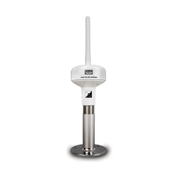
A Class B transponder is required to derive its position from its own internal GNSS receiver rather than an external feed, so the supplied GPS antenna has to be fitted properly and cannot be substituted with a shared position source. It needs an unobstructed view of the sky: not under a hardtop, not in the shadow of the mast, not tucked beside a radome. A poorly placed GNSS antenna does not usually produce an obvious failure. It produces a position that is intermittently degraded, which means the position you are broadcasting to everyone else is the thing that suffers. Digital Yacht's GV30 solves both antenna problems in one fitting, combining a VHF element tuned to 162 MHz and a GPS element on a standard 1 inch threaded base with twin 10 m coax tails.
Cable runs and connections
Coaxial loss is cumulative and irreversible, so keep runs short and use good-quality cable, stepping up to a lower-loss type on long runs rather than accepting the loss. Every connector is a potential failure point and a water ingress path: make them up properly and seal any that live outside. Route coax away from power cables, the alternator and any inverter, and avoid tight bends. Terminate to whatever the equipment actually uses; AMEC receivers and transponders in this range use an SO-239 female VHF connector, while Digital Yacht antennas commonly ship with BNC and TNC adaptors.
A working sequence
- Plan both antenna positions before drilling anything, checking sightlines to the sky for the GNSS antenna and separation from other antennas for the VHF one.
- Mount the antennas and run the coax, leaving a drip loop and a service loop at each end.
- Mount the transponder somewhere dry, accessible and within reach of both cable runs, respecting the compass safe distance quoted for the unit.
- Wire power from a dedicated, correctly fused circuit rather than sharing a breaker with other electronics, since the transponder draws a current peak on every transmit burst.
- Connect the data interface to the chartplotter or PC over NMEA 0183, NMEA 2000 or Wi-Fi, as the installation requires.
- If a splitter is used, connect the VHF radio to the splitter's radio port and confirm the radio still transmits and receives normally with the transponder both powered and unpowered.
- Program the static data: MMSI, vessel name, call sign, dimensions and antenna reference position.
- Confirm operation with the manufacturer's configuration software, such as Digital Yacht's ProAIS2, checking that the unit has a GNSS fix, is receiving targets on both channels, and is transmitting.
Commissioning checks worth making
Once it is running, compare your target picture against what you would expect: if you can see a large ship visually but not on AIS, something is wrong with the receive path. Check that your own transmission is being picked up, either by another vessel nearby or via the transponder's own status reporting. Verify that the static data reads back correctly, since a wrongly entered MMSI or a transposed dimension is easy to make and invisible from your own bridge. On splitter installations, check that the splitter fails safe, so a powered-down transponder does not leave the VHF radio without an antenna.
ASPL supplies and integrates the Digital Yacht and AMEC ranges in India and handles NMEA 0183 and NMEA 2000 interfacing between AIS, navigation, autopilot and charting systems as part of a fit, including commissioning and handover to bridge crew.